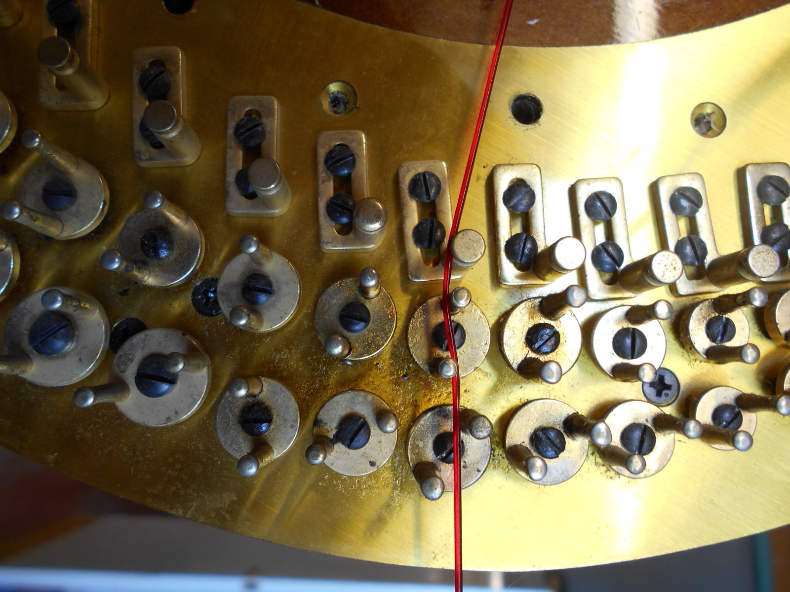
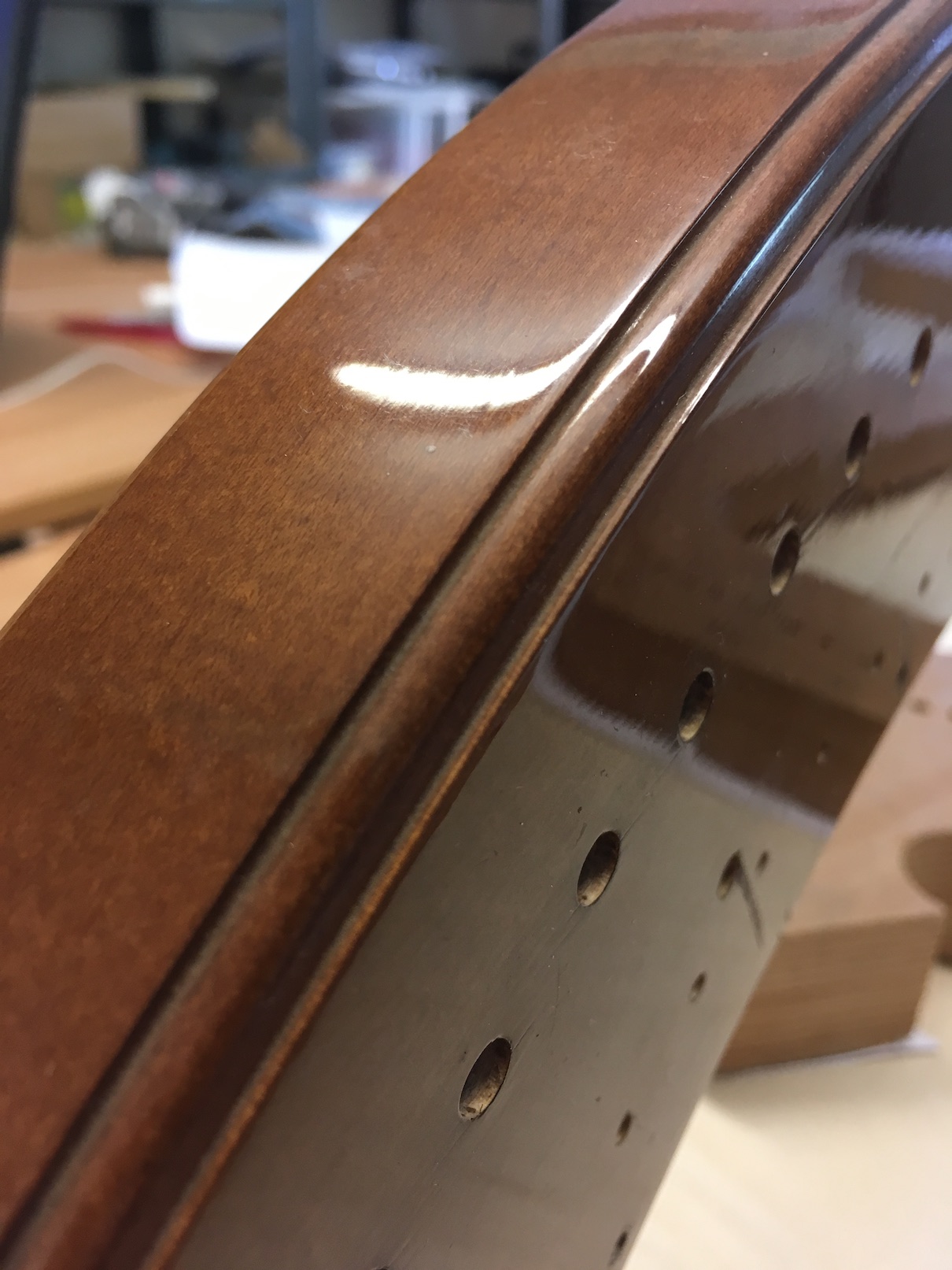
Fig. 1 - string should fall through the centre of lower pins when the top set is engaged:
This document is intended to act as a guide to a standard neck repair on a pedal harp. There is obviously huge variety between makes of harp, and while some of the more common problems/differences are addressed here, it must be remembered that there will always be exceptions that require the repairer to deviate from the process outlined below. An approximate timescale for the following repair would be 3-5 weeks (including time for settling and regulation), assuming no unforeseen problems.
When making a new neck for a concert harp, it is important that the replacement neck remains as close to the original neck profile as possible and that it is aligned in the same position.
In order to ascertain the shape that the new neck will need to be, it is first necessary to temporarily repair the original neck so that it may be used as a reference for the replacement. As the old neck may have dropped under the string load and weight of the mechanism, however, it is important not to follow exactly the same distorted form when constructing the new neck.
NB The following can only be done if the original neck retains enough strength and shape (i.e. it's only cracked, not completely broken) to allow the position of the neck and mechanism to be checked for accuracy. In cases where this is not possible due to the damage being too great, this will have to be done after the original broken neck has been temporarily repaired and the harp reassembled.
Video 2: Checking accuracy of tuning:
First, check the accuracy of the tuning with the pedals in all three positions. The pitch difference between flat and natural can be modified by the adjustment of the bridge pin, but the distance between natural and sharp cannot be adjusted as the spindle centres are fixed. You should therefore use the sharp note as your reference note for pitch (unlike under normal tuning circumstances where Cb is the usual reference point for pitch on modern concert harps) as if this note is inaccurate it is extremely difficult to compensate for it later on.
If the neck is too low (particularly in the treble end) the notes will sound higher than they should do when the pedals are in the sharp position due to the speaking length of the string being shorter than it should be.
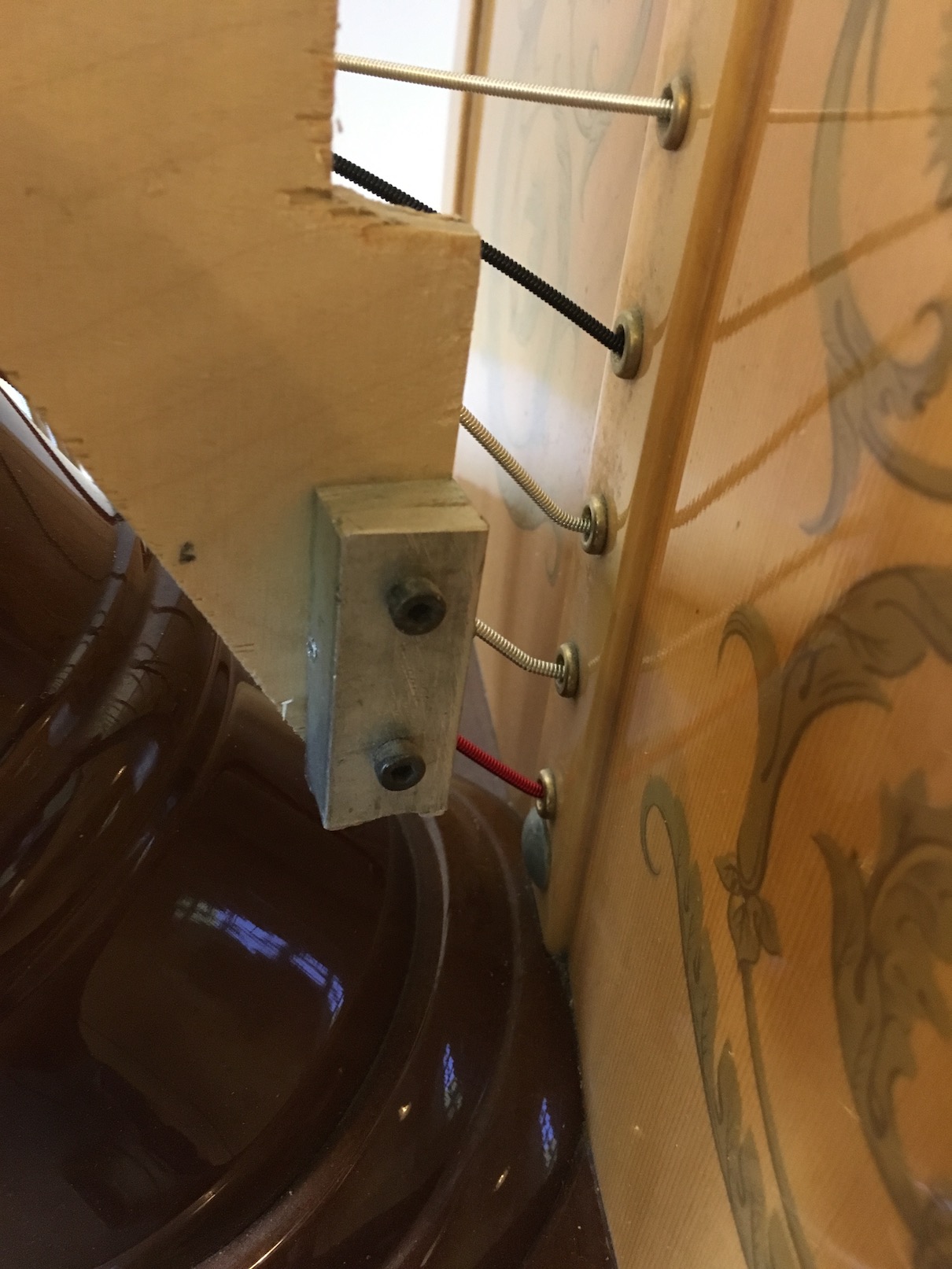
It is also important to ensure at this stage that the strings pass through the exact centre of the second (lower) set of disk-forks when the pedals are in the natural position (i.e. the upper disk is engaged - see fig 1).
Fig. 1 - string should fall through the centre of lower pins when the top set is engaged:
(NB They will not fall through the centre of the second set of pins when in the flat position - only when the pedals are in the natural position will they come to the centre of the second set. When in the flat position the string should fall through the exact centre of the first (upper) set of disk forks
If the string does not fall in the centre as described above, (though it usually does) it is possible to compensate for this later when positioning the new neck on the top of the soundbox, although it is obviously preferable not to have to do this.
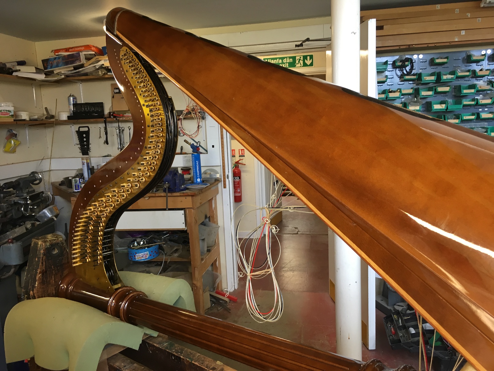
Unwind the strings so that you can remove them from the tuning pins, and then tie them out of the way (fig. 2). Now remove the tuning pins from the harp (NB: remember to thread the tuning pins onto a piece of wire so that you can put them back in exactly the same order - conventionally this is treble-bass).
Fig. 2 - harp on stand and stings tied up out of the way:
It must also be remembered that different makes of harps will have different gradients of taper on their tuning pins. Generally the non-metric harps will have a taper of 1 in 48, whereas harps made using the metric system will have a taper of 1 in 50. It is important to know this when you come to ream the holes in the new neck, or if new pins need to be made.
Rest the harp on a suitable frame (fig. 2). Remove the bottom of the pedal box (usually the tuning key can be used for unscrewing this) and remove the pedal rods from their attachment to the mechanism by releasing each of the seven clevises from the bottom of the pedal rods and unscrewing the pedal rods anti-clockwise.
Mark each pedal rod so that they can be identified later. For ease of assembly in the later stages it is useful if the clevis position is also marked on each pedal rod so that they can be put back as far (as is possible) in the correct place (see video).
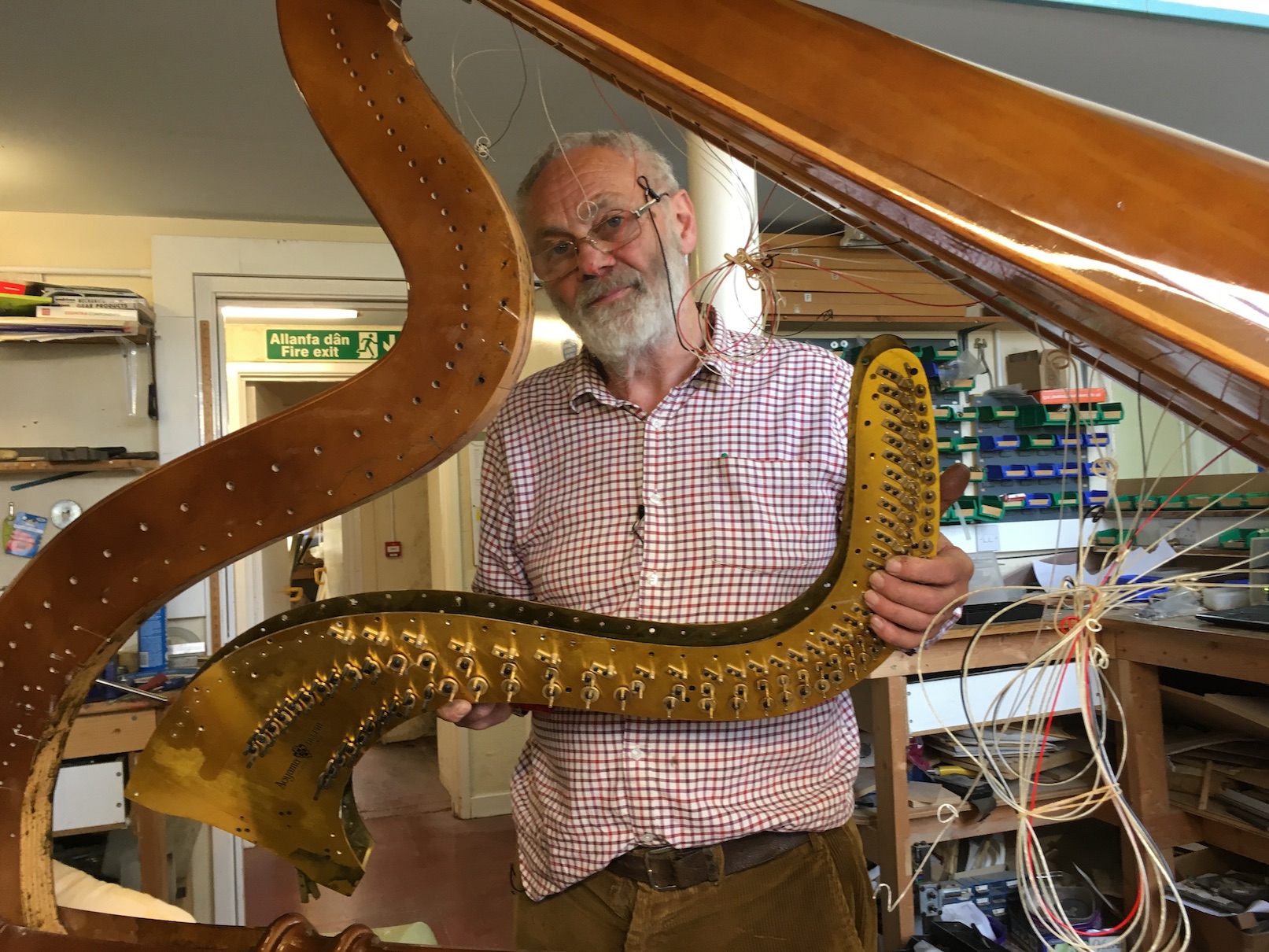
Now that the pedal rods have been detached, it is time to remove the mechanism itself.
At intervals along the mechanism plate, you will find plate-retaining pins with a screw head (fig. 3) which will need to be removed. In order not to damage the screw head, you should use a special punch (fig. 4) which goes to the bottom of the drilled and threaded hole to remove these.
Fig. 3 - plate removing pins:
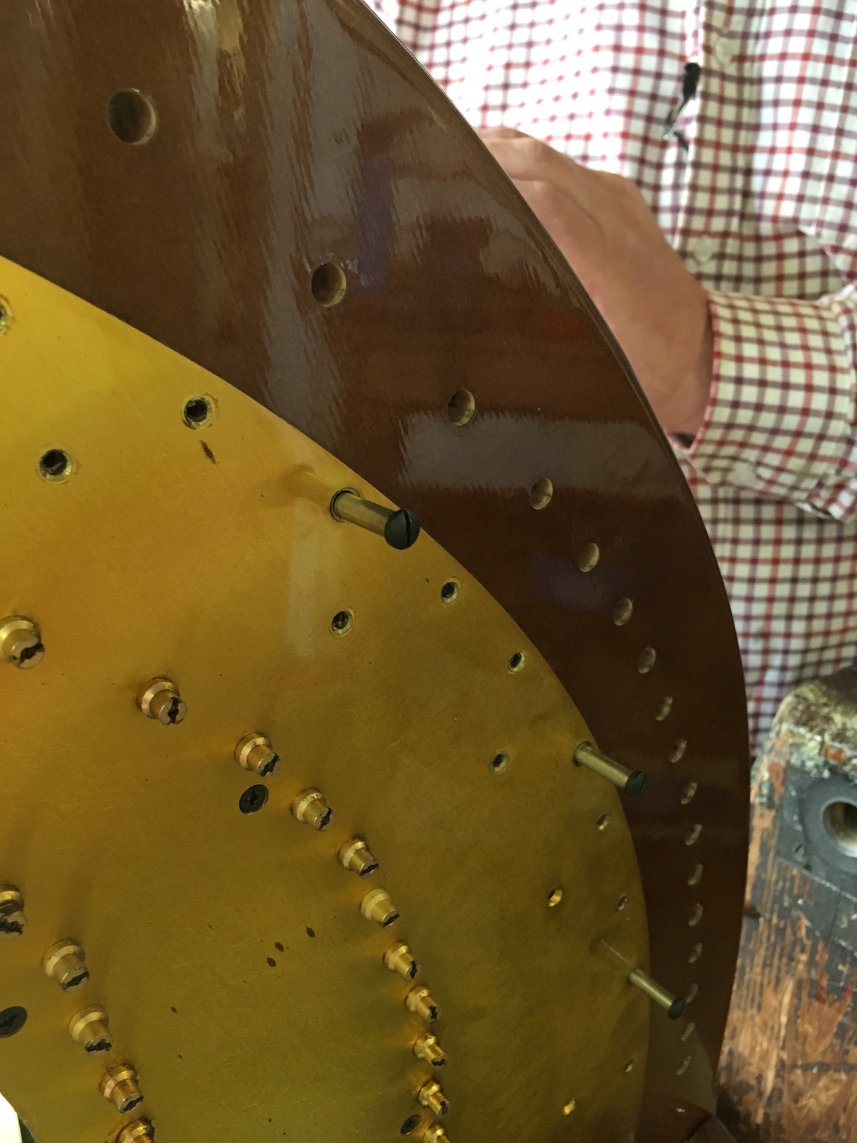
Fig. 4 - unscrewing the plate and neck mechanism:
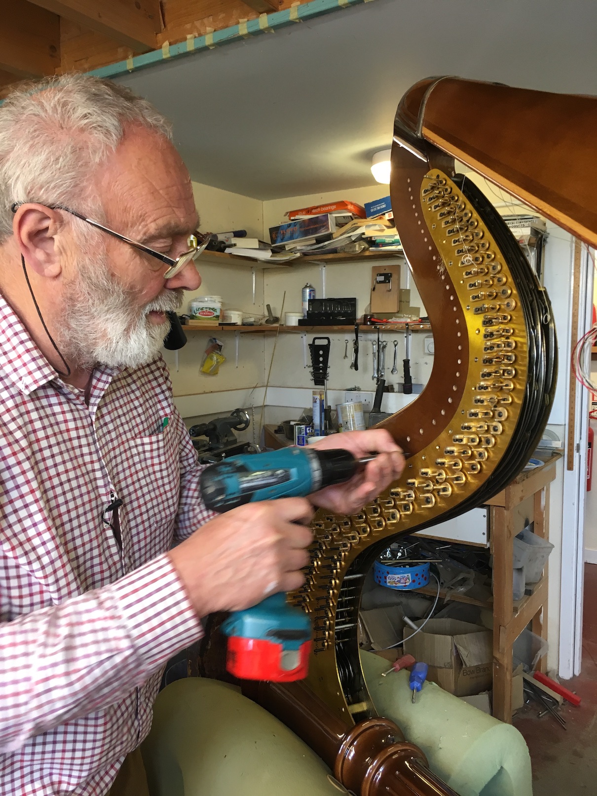
Be careful at this stage to take out only the screws that hold the mechanism in place - there are also a large number of screws which are holding the mechanism together, and these should be left alone. The relevant screws will be along the top of the plate, running along the line of the harmonic curve.
You should also be aware that you will often find a number of different styles of screw heads holding the mechanism in place: some will be Phillips and others will be Pozie-Drive (there is a 15 degree difference in the angle of the screwdriver).
There may also be some wood screws and bridge pin screws that will need to be slackened in order for the mechanism to drop from the neck. Note that the last bridge pins for the bass wires will need to be unscrewed completely as they go into the wooden neck. Place all pins and screws into a peg board so that they go back in the same order on the completed repair.
The mechanism should now swing down and clear the sound box (fig. 8). If it does not, you may have to remove the neck and column entirely from the soundbox to get it off.
Fig. 5 - the mechanism removed:
If there is room, a way to effect a better repair to the harp is to use larger (6mm diameter) plate-retaining pins when constructing the new neck since there is a tendency for the smaller 3/16th (or 5mm ) pins to sheer off under load.
Wherever possible, the entire neck should be removed at this stage. This is done by releasing the two angled screws at the top of the column located under the crown (fig. 9), before taking out the central coach bolt.
Fig. 6 - removing angled screws and central coach bolt:

Once this is done, it should be possible to lift the neck off the soundbox (fig. X). If it is not possible to remove the neck (because it has been glued into the column, which can sometimes be the case) then it will be necessary to dismantle the harp by removing the (still joined) neck and column from the soundbox and base. It should then be possible to temporarily repair the broken section of the neck whilst it is still attached to the column. It will of course be necessary to separate the old neck from the column at a later stage, but it is important to do this only after an accurate template has been made (see below) as you may damage the old neck in detaching it and thus affect the alignment, which you will need to measure accurately.
Fig. 7 - the neck removed!
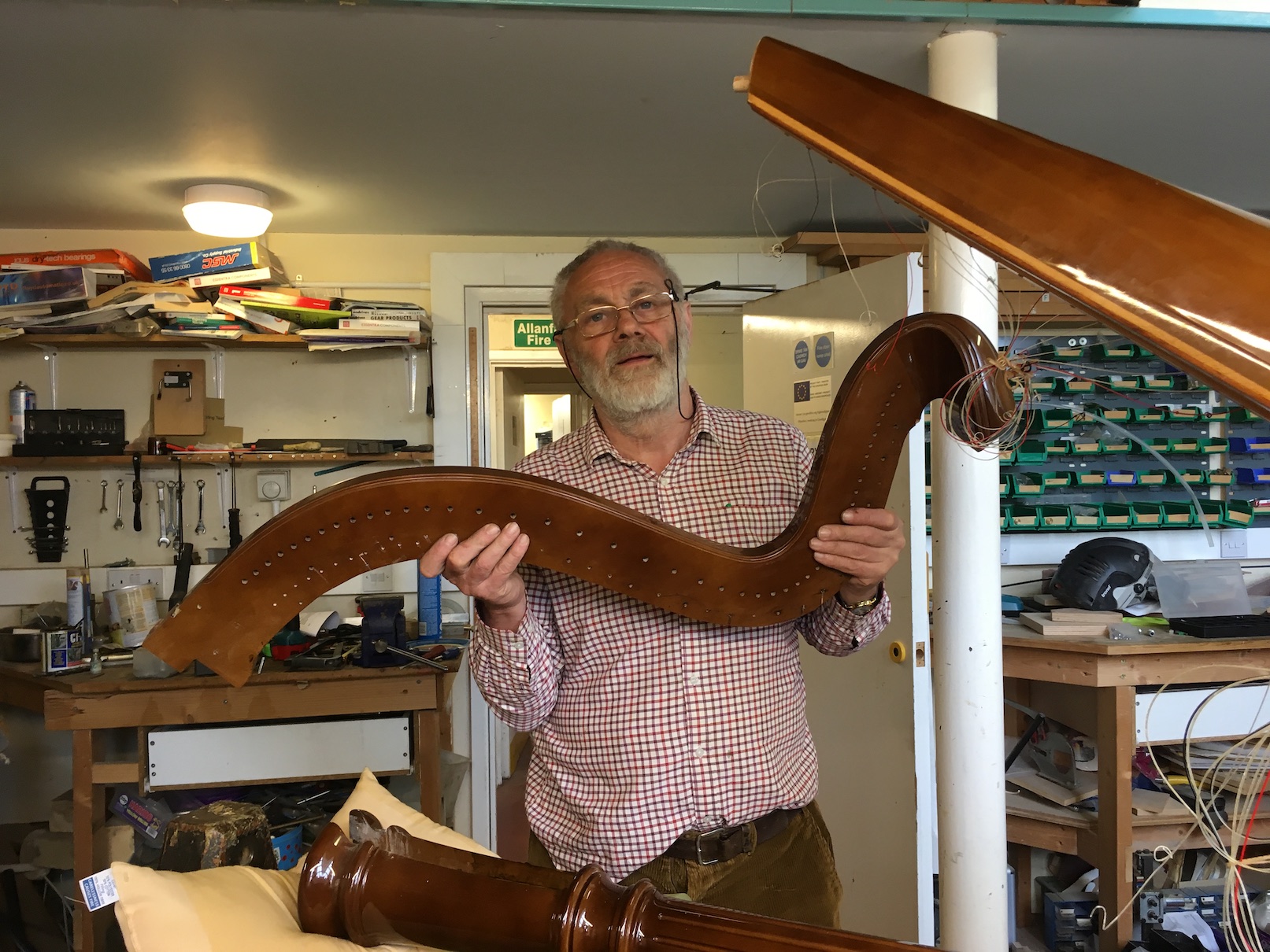
In order to make a template for the new neck, the old neck (once removed) must then be dry-assembled to as close a shape as possible to its original form.
After the neck has been temporarily glued and repaired, the harp must then be reassembled to allow a plywood template to be made (see next step).
If it was possible earlier (step one) to check the accuracy of the neck and mechanism position, move to the next step. If not, see below:
In cases of severe damage where step one could not be completed:
If it was not possible at the beginning to check the accuracy of the neck and mechanism position (so that adjustments to placement can be made if necessary during the repair), this must be done at this stage.
Re-assemble the harp and replace the mechanism and pins. Re-attach the strings to the pins (at a minimum the Cs and Fs) and tune them as standard (i.e. to Cb and Fb when the disks are disengaged). You can now check for accuracy of pitch as described in step one.
With the original neck (now temporarily repaired), column and box back in place, it is now time to make a plywood template of the curve of the neck and the relative positions of the pins and mechanism attachment holes. (If you needed to reattach the mechanism in the previous step, it must now be removed again).
If the damage in the original neck is only minimal (and retains its original shape) it is possible for the experienced repairer to omit this step and use the original neck alone as a template for drilling holes for the tuning pins and mechanism attachment.
You will need to attach two pins to this template - one at the top and one at the bottom - which will slot into the top and bottom string eyelets of the soundboard (figs. 8, 9, 10, 11) to keep it in place. The whole template is then clamped in position over the old neck on the left-hand side (i.e. the disk side).
You should now drill into the plywood through the existing tuning pin and mechanism attachment pin holes (see video) to give reference holes in your template to use when making the new neck. From these holes we can drill the appropriate diameters for the tuning pins and mechanism-fixing pins into the new neck.
Fig. 8 - plywood template:
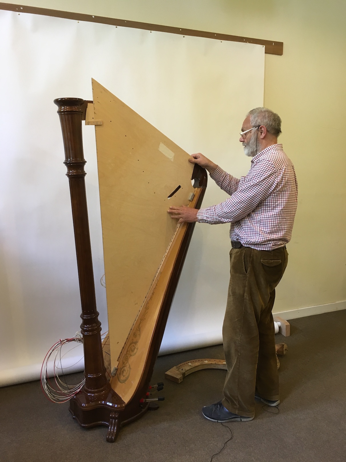
Fig. 9 - pins on plywood template:
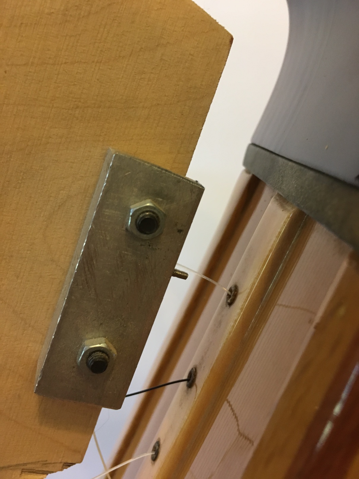
Fig. 10 - pins slotting into top eyelets:
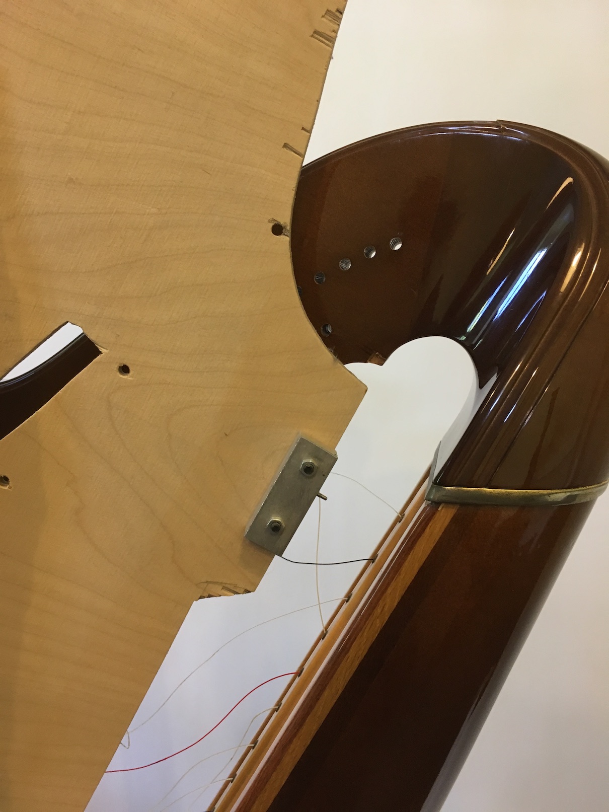
Fig. 11 - pins slotting into bottom eyelets:
Ideally, the new neck should be constructed from approx. 6mm rock maple segments. The finished neck will contain approximately ten layers (depending on the shape and size required).
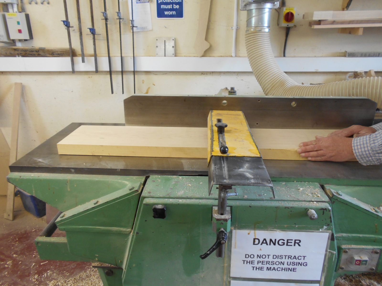
You will first need to prepare your 6mm segments. Using a plank of rock maple, flatten the sides and then slice it into segments.
Fig. 12 - flattening the plank of rock maple to deep cut the 6mm segments:
Remove the old neck again. If you were unable to detach it from the column earlier, this must be done now. All relevant measurements should now have been taken, so it does not matter at this stage if you damage it during the removal process.
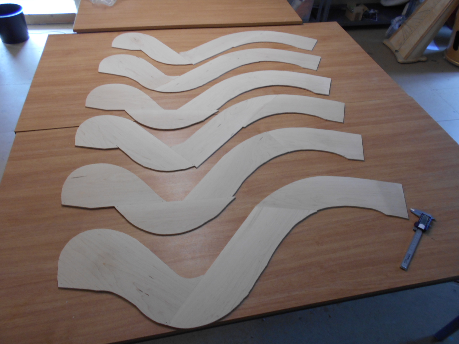
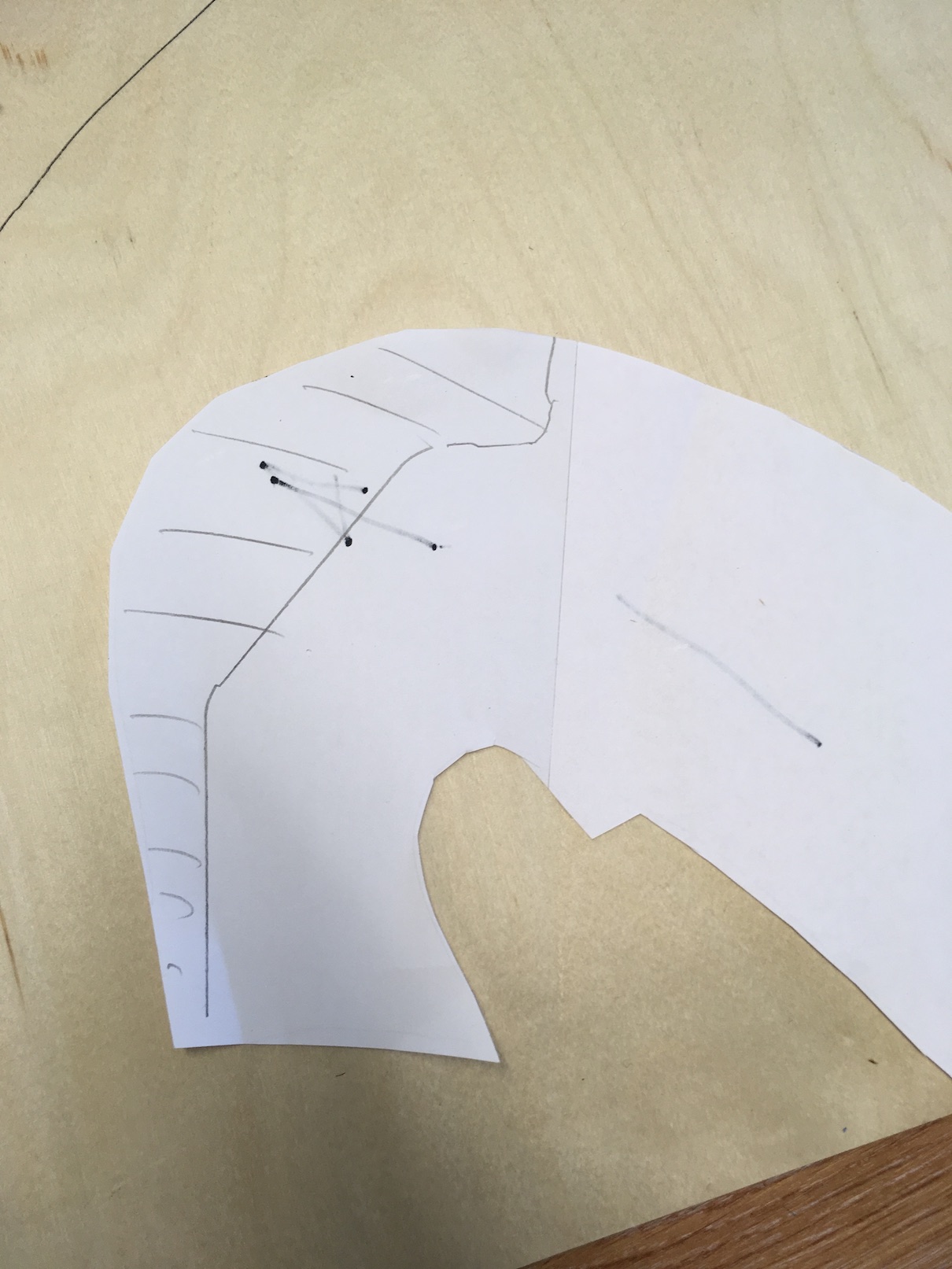
Draw round the shape of the old neck onto a thin piece of plywood to make a template. You will also need to make several paper templates of this same shape (fig. 13).
Fig. 13: paper cutouts for making the new neck segments
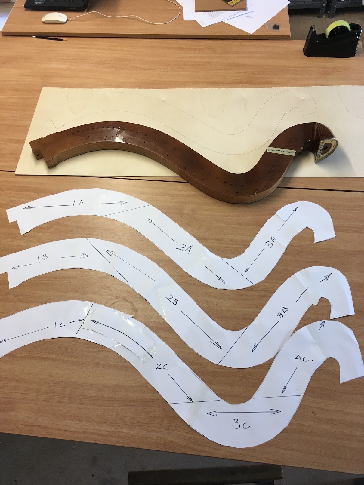
Using the paper cutouts, draw lines as shown in fig. 13 so that the grain of the rock maple segments can follow the harmonic curve to ensure optimum strength in the finished neck.
Cut out the segments of rock maple using your paper shapes as a template, making sure that the grain follows the arrows as shown. Make sure that you allow an extra margin of approx. 15mm on the outsides of the harmonic curve (i.e. the sides that will become the top and the bottom of the neck) when cutting out your maple in case it slips during the gluing process - you can cut away any excess one it&aps;s securely glued.
When you come to assemble these layers, it is vital to ensure that the segments overlap as shown in fig. 15, so that that the different layers of rock maple will have joints in different places. This ensures that the neck will be as strong as possible (similar to the principle of building a brick wall).
Fig. 14 - segments of neck cut out ready to be aligned:
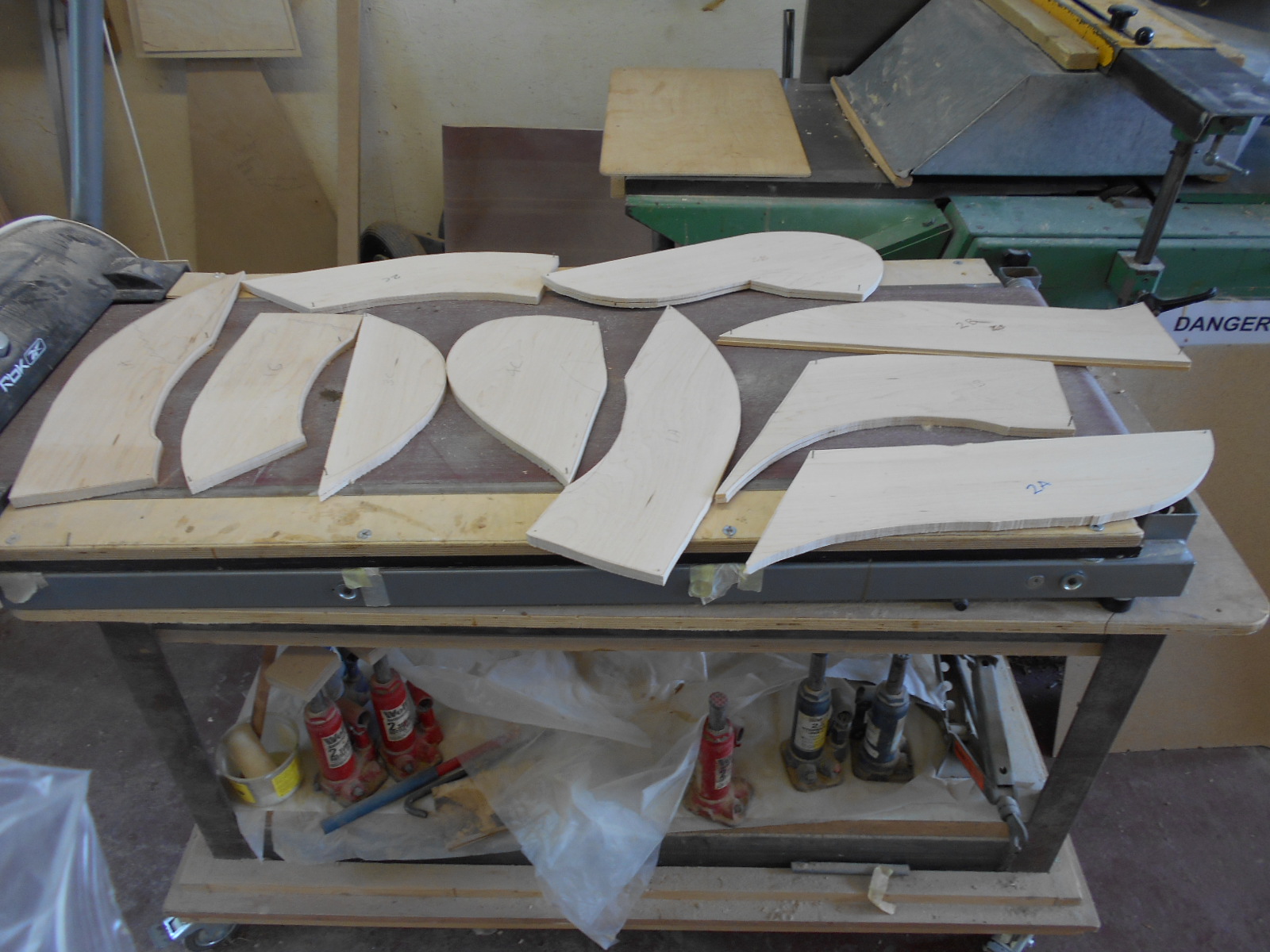
Fig. 15 - segments of neck aligned as described above. When assembled, all the joints will overlap to ensure maximum strength:
Glue the individual segments of each layer at the joints using West Systems epoxy resin (we think it's the strongest!) ((see fig. X above). When the glue is dry, pass each segment through a sanding machine to ensure everything remains parallel. You can then ascertain approximately what the finished thickness of each segment will be.
As it is essential that the finished neck is exactly the same width as the original in order for the mechanism to fit and work properly, do not forget to take into account that it will also need to be veneered and lacquered. Each veneer, sanded, will add 0.5mm, and the lacquer will add a further 0.5mm on each side (2mm in total).
When you are happy with the general thickness (having taken into account your additional 2mm of veneer and lacquer), the segments need to be assembled in the correct order (i.e. with overlapping joints) and glued overnight in a press with hydraulic jacks. Where it is possible, it is preferable to use a locating dowel pin (plastic acetal dowel) in a place that is not load-bearing so that the layers do not slide out of alignment whilst being glued in the press (Diagram A).
Fig. 16 - layers of new neck glued together:
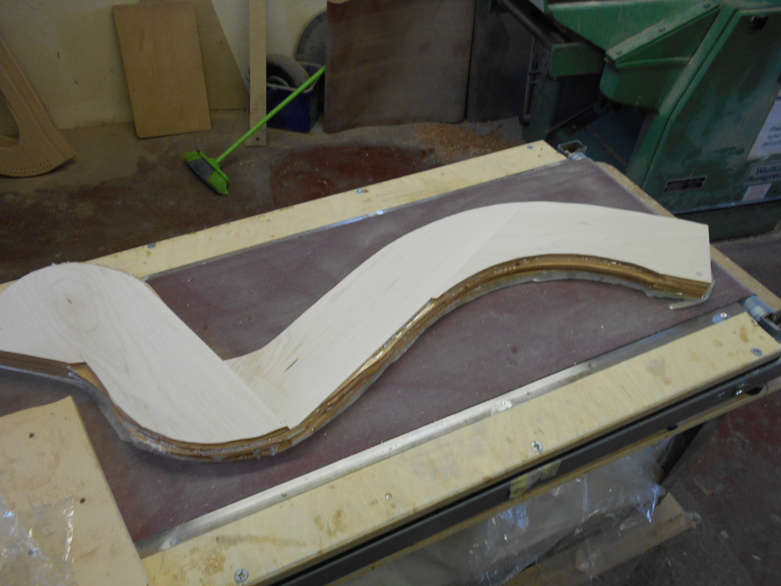
Diagram A - locating dowel pins in neck to avoid slippage during gluing:

Fit the new neck onto the column and soundbox and, using the triangular plywood template (or the old neck, if in a good enough state of repair to omit the use of the plywood template), as a guide, mark and drill the locating holes for the mechanism and tuning pins.
If using a plywood template, you must ensure that it is slotted into the eyelets of the soundbox (as shown earlier in step six) and clamped to the new neck.
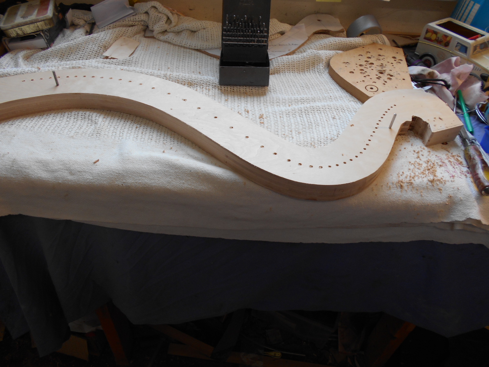
These reference holes can now be drilled on a drilling machine to make sure that they are accurate. Note that at this stage the holes for the tuning pins will need to be reamed approximately to depth from the offside (RH side).
Fig. 17 - marking and drilling holes for mechanism and tuning pins:
You now need to check the final thickness of the neck (now out of the press and drilled), and if no adjustment is required it should be sanded. (If the neck is too thick at this stage, it can still be sanded down to the correct size before the veneer is added).
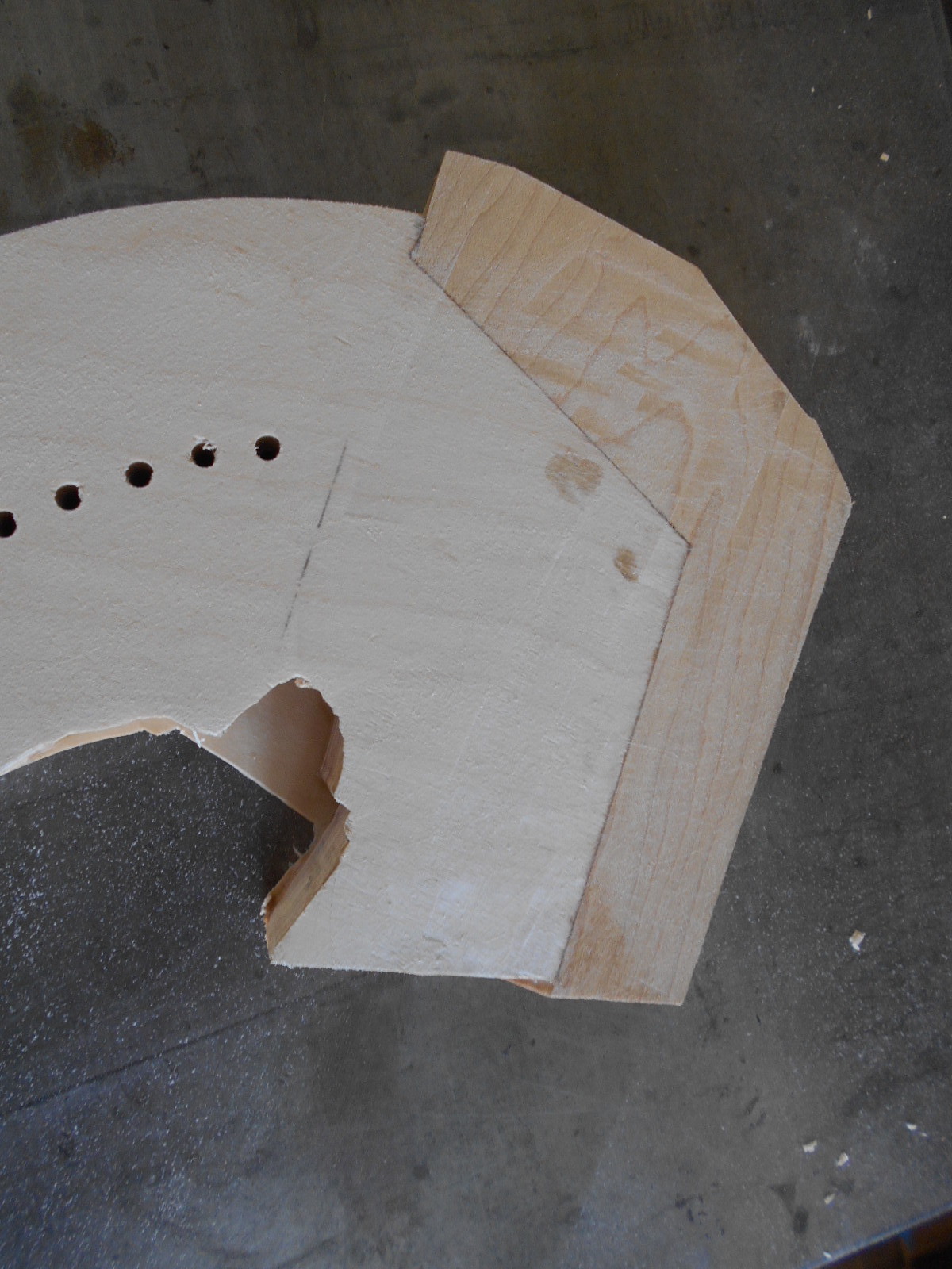
You then need to prepare the neck for the cheekpiece by cutting an angular profile into the treble end of the neck. This is where the 3D profile of the top of the soundbox becomes the 2D profile of the neck. First, PREPARE A TEMPLATE USING THE ORIGNAL NECK AS A GUIDE ((figs. 18, 19).
Fig. 18 - preparing the template:
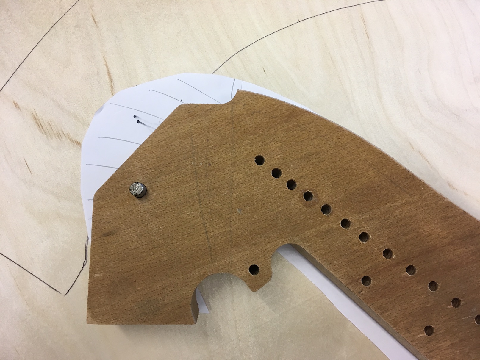
Fig. 19 - paper template of profile to cut:
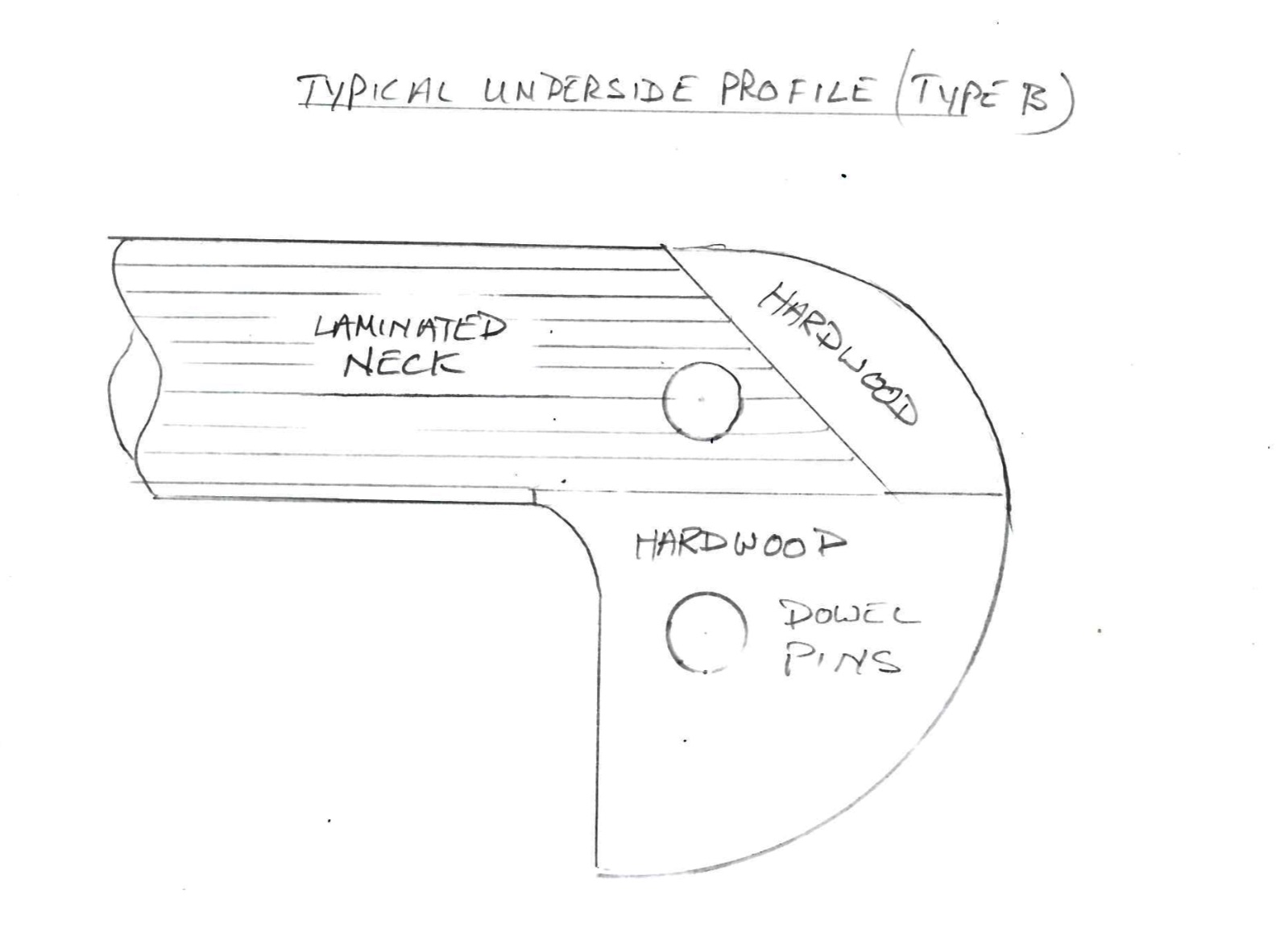
This angular joint is the central part of the cheekpiece. The rest of the cheekpiece (depending on the model of harp, this will need to be done in two or three further 3D segments - see the diagrams below showing common underside profiles) will be added later.
Diagram B - typical underside profile of cheek (type A, with cheek made in three sections:
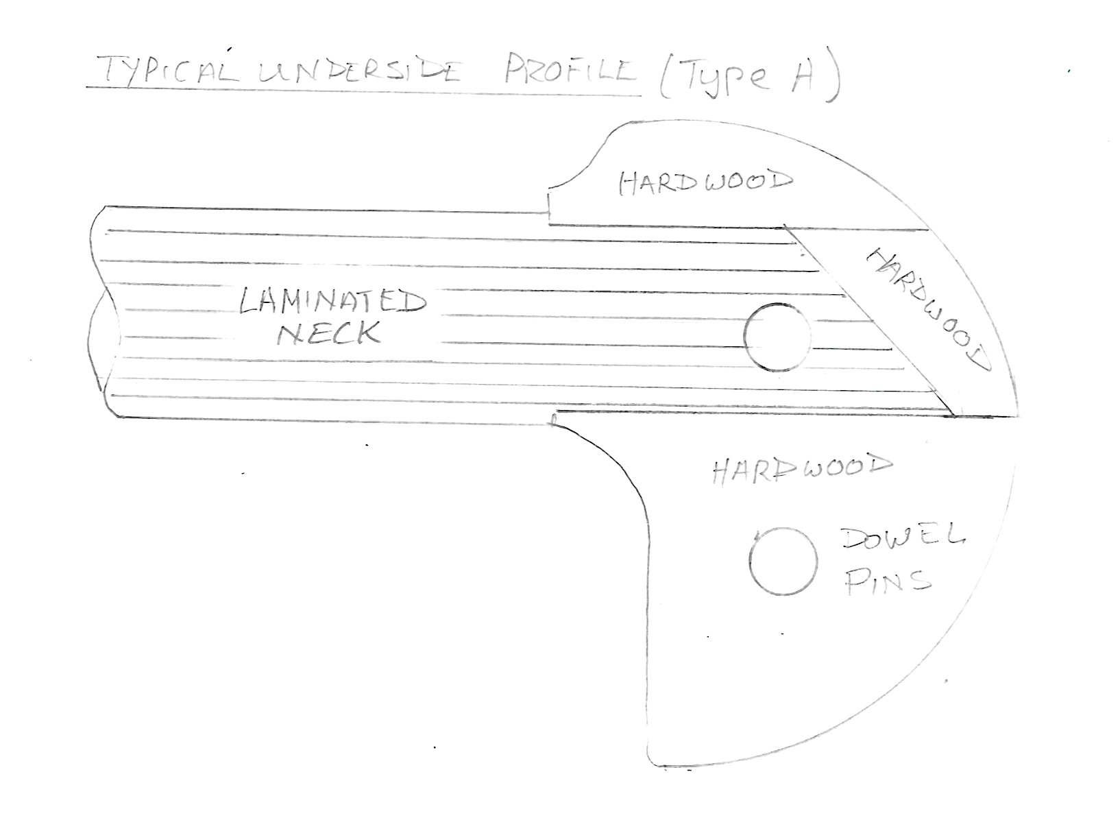
Diagram C - typical underside profile of cheek (type B, with cheek made in two sections):
If a groove is required along the top of the neck, as shown in fig. 20 (below), this must be formed with a router at this stage. Depending on the type of harp, this may be done before or after the veneering process.
Fig. 20: - moulding along top of neck:
When you removed the neck from the soundbox, you will have noticed two (occasionally only one, but two is more usual) pieces of dowel protruding which held the neck and cheek piece in position (as shown in ‘neck removal' video).
We now need to ascertain where the to make the corresponding hole in the neck to accommodate the piece of dowel which will hold it in position. (The next, larger cheek piece(s) (the main 3D form) will be added at a later stage, and drilled accordingly to accommodate the second piece of dowel, where applicable ).
Reassemble the harp again (you do not need to reattach the mechanism), and, using your triangular plywood template from before (if applicable), mark the position of the relevant dowel pin on the neck. Remember that the neck needs to be offset from the centre of the soundboard by the same amount as the original. (This is in order to ensure that the strings to hang vertically down from the bridge pins of the mechanism.
A top strip (fig. 21) is now normally added. Usually, this is done after the central cheek piece has been fitted. It is more usual to veneer the side pieces after the top strip is added (though occasionally these processes may need to occur the way round depending on the type of harp).
The top strip is made of maple (or other suitable timber) which should be steamed into the correct shape, following the harmonic curve.
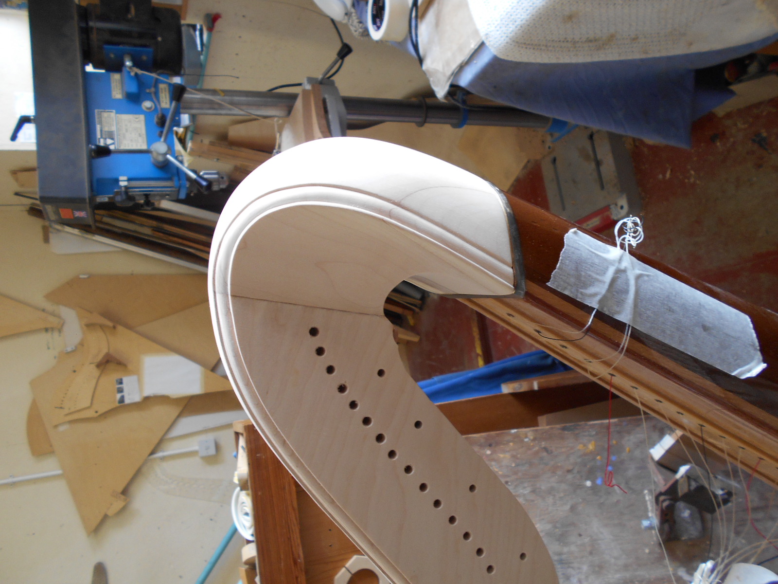
Fig. 21: - the top strip. Note the semi-circular shape at the treble end (see next photo for more detail):

You will need to cut a semicircular shape (as shown in fig. 22) at the treble end of the top strip (where it joins the cheek piece). This will help to cover any movement at the glue line in later years.
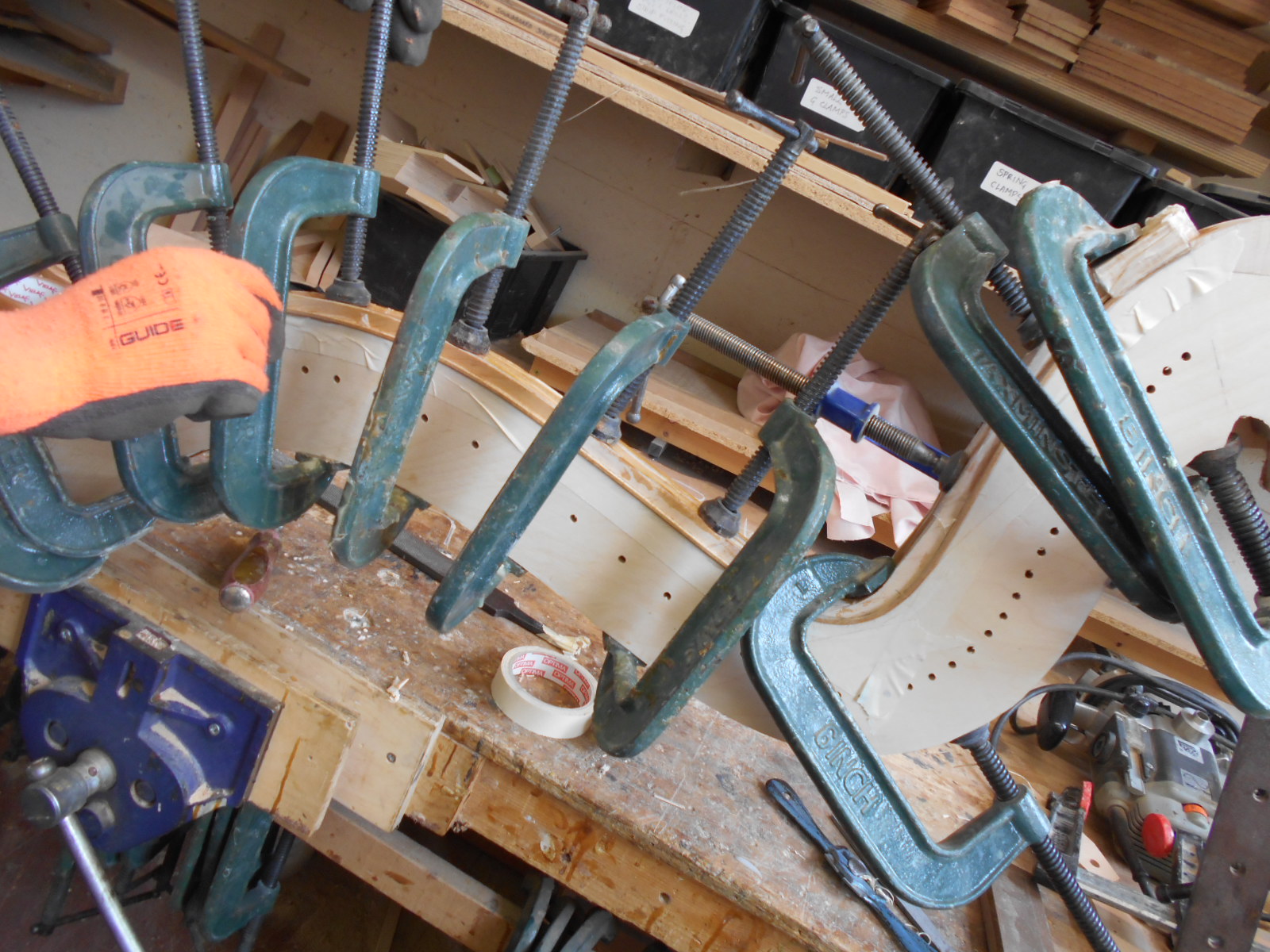
The top strip should now be glued in place and clamped. (fig. 23).
Fig. 22 - the preparation where the cheek piece and the top strip join:
Fig. 23 - clamping the top strip (the residue cut earlier from the top of the neck can often be used as the pressure pad as it is the same profile. Sometimes a rubber strip may also prove to be useful):
The cheekpiece is made out of a piece (or pieces) of maple (or other suitable timber), and will form part of a mortice and tenon joint cut by hand to the opposite profile of the neck, which should have been cut in step ten (fig. 24).
Fig. 24 - new neck with one cheek piece added:
It is left as a square block (or partially formed) and glued in place after the neck has been veneered and the top strip put on as just described in step eleven. It is then formed to the shape needed by hand. It is important that the underside of the cheek-piece fits exactly onto the top of the sound box (ie they are in the same plane) (fig. 25).
Fig. 25 - remaining cheek piece ready to be glued on:
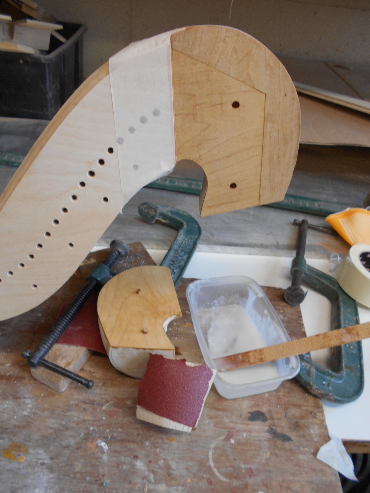
Fig. 26 - cheek piece carved to match moulding on neck:
After checking the correct position by reassembling the harp, the second dowel hole (if there is one) can now be drilled on the underside of the cheek piece.
The metal top cap (see (fig. 27)) can now be put onto the dowel pins and used as a reference for the underside of the cheekpiece profile. (The cheek should slightly overlap the top cap - see fig. 28).
Fig. 27 - metal top cap:
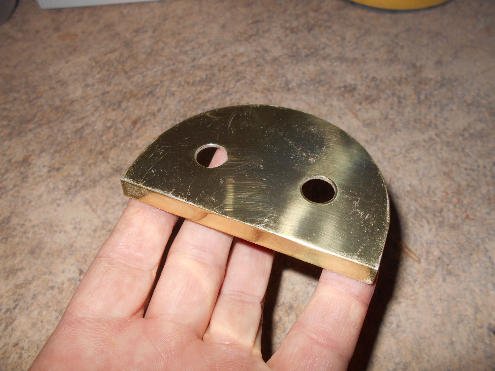
Fig. 28 - note slight overlap of cheek onto top cap:
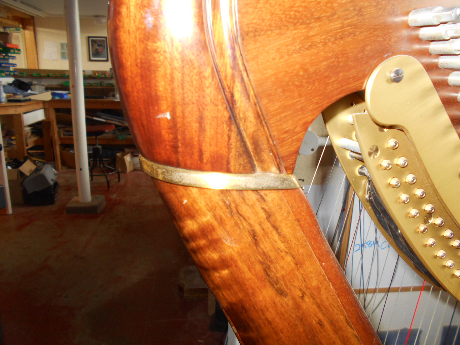
Having marked the underside of the cheek piece, it can now be carved into its finished shape. If there is moulding on the neck, this will need to be cut by hand into the finished cheek piece, continuing to follow the curve round to the top of the soundbox (fig. X).
When putting the dowel pints in to align the neck with the top of the soundbox, it is worth putting the mechanism back on and double-checking the horizontal alignment for the strings through the centre of the disk forks (as described in step one). NB The sharp note should be used as reference for pitch - see step one.
Normally, necks are made in rock maple and need be finished to match the rest of the harp. This is best done by a trained wood finisher who will be using a combination of stain and lacquer for the final result.
Once the neck is finished the harp will need reassembling, the pedal rods connected, the over motion set, tuning and regulating to the tempered scale once the harp has settled.
Overmotion is set by adjusting the pedal rod length so that when the pedal is in the natural position the natural disk stays absolutely stationary. The reason for this is that should that central position move when pressing the pedal to sharp, inaccuracies will occur in the regulation. Bear in mind that the mechanism will need lubrication of all the moving parts before being reattached to the neck.
Assuming full-time work, and depending on the type of harp and the complexity of the repair required, this process should take approximately 3-5 weeks. This is including regulation and allowing a week to settle before making any final adjustments. This is also assuming that no adjustments need to be made to the mechanism itself.